Please be aware that unless an engine has been modified to accept post-war thin-wall shell bearings, bearings for all pre-war engines require work to fit them to the relevant housing. All bearings then need to be machined to suit the crankshaft.
The crankshaft bearing shells that we manufacture for pre-war Rolls-Royce engines consist of a bronze or steel backing which is lined with white-metal or Babbitt (different names for the same product). Different grades of white-metal are used, depending upon the application.
The bearings are manufactured as a complete ring, which is then cut or split into two ‘shells’. Before the ring is split the outside diameter is machined to be very slightly bigger than the internal diameter of the housing to which it is to be fitted. The difference will be about 0.001” – 0.0015”. This should ensure a slight interference fit between the shell and the housing.
It is most important that the shell is fitted to its housing with the correct amount of bearing ‘nip’. The nip is a measure of the amount by which the shell is gripped in the housing when the bolts securing the bearing are tightened. In effect the length of the outside circumference of the shell should exceed the length of the internal circumference of the housing by an amount of about 0.001” – 0.0015”. This is achieved by removing material from the butt faces of the shell until the bearing nip is correct. This requires considerable skill and experience to do satisfactorily.
Once the bearing shells have been fitted to the appropriate housing with the correct bearing nip the internal diameter is machined to give the correct running clearance when fitted to the crankshaft. If this operation is completed correctly there is no need to scrape the bearings after machining before building the engine. The bearings have sufficient white-metal in the bore to allow for machining to final size.
The act of splitting the shells during their manufacture removes material from the initial ring, resulting in each shell being less than a full semi-circle. To make up for the width of the saw cut flat piece of metal of a precise thickness, known as a bearing ‘shim’, is positioned between the opposing butt faces of the two shells, one on each side of the bearing. The shims are also clamped between the bearing cap and the main body of the housing, which may be either a connecting rod or the crankcase. As well as making up for the material lost when the bearing ring is split, the shims also prevent the bearing shells from spinning in the housing.
Connecting rod
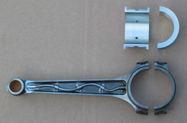
The picture shows the connecting rod and cap, and the bigend shells to be fitted to the rod
Bearing shells
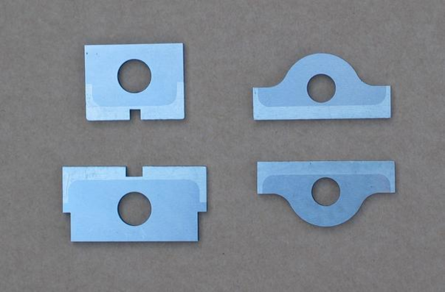
Main bearing shims are shown on the left, bigend shims on the right. The steel shims are edged with white-metal along one side.
Bearing shells with shims
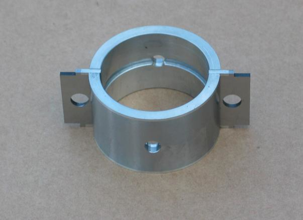
This picture shows a pair of main bearing shells with shims in position.